Muxtronics Powerbank (Rev. 3+)
This is a comprehensive technical manual for the programmable Muxtronics Powerbank. This powerbank supersedes the non-programmable 12V powerbank. This powerbank outputs - as you expect - 5V/2A to charge regular mobile devices, but also outputs 12V/3A on the 'HV' port to charge large tablets or be used as a UPS (Uninterruptible Power Supply) for e.g. Raspberry Pi, networking equipment, etc. The UPS functionality means the powerbank can charge and output at the same time. Maximum draw to maintain battery level is 12.5W (avg.).
Besides having UPS and 12V capability, the powerbank also offers a plethora of programming capabilities. The HV output can be varied from 9.5-24V at constant power (36W). Via either the onboard serial port or via the USB charge port, current consumption (on both USB and HV), HV output voltage, charge rate and battery voltage can be read, continuously. Configurable alarms can warn the user of loss of power. Uptime can be read. The brightness of the indication LEDs can be changed (as can the PWM frequency). Individual outputs can be enabled or disabled, low battery levels can be modified, charge rate can be changed as well as many, many, many other settings.
If this is not enough functionality yet, the powerbank can run user-developed programs using a custom bytecode. This allows the user to interface up to 9 GPIOs (among which 5 0-1.0V ADC/analog comparator inputs, 2 PWM outputs and a TTL 3.3V UART), respond to any combination of inputs or state changes, modify LED behaviour, HV output voltage, output switching. Anything the powerbank can do can be programmed. If this is still not enough (and this is getting a bit silly now), the PDI programming port is right there on the PCB and the MCU is fully unlocked, so you can run any program that fits in a Microchip ATXmega32C4.
Option boards can use the programming header to mount to and communicate through. Currently, there is only an ESP8266 option board for wi-fi functionality.
Specifications
(to be populated)
Overview
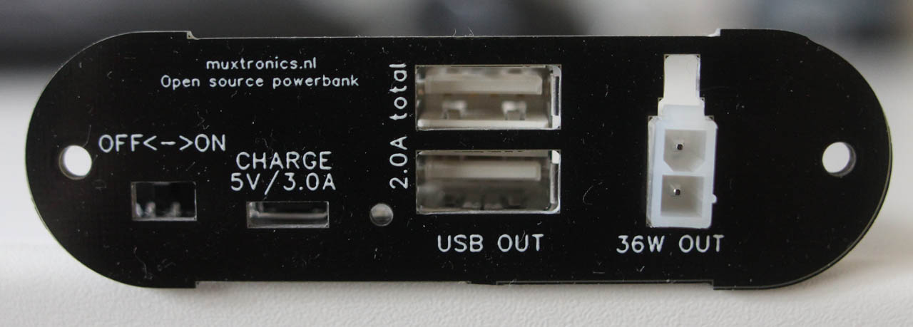
The powerbank has the following interface elements:
- The on/off slider. When off, the output ports are off (Rev. 3: battery voltage is present on the outputs). When on, by default both outputs are turned on and the HV port lights up blue.
- The charging port (micro USB 2.0). By default, the charging port is configured to draw up to 3.0A. This requires good quality cables. When plugged into a computer, the powerbank enumerates as a virtual serial port (CDC device) and allows serial communication over USB via the supplied application.
- The red/green indication LED. By default, this LED lights up yellow-to-red (using color mixing) when the battery runs low or when charging. Fully red means very low battery (set by Vcrit setting, default 3.08V), yellow means low battery (3.30V) and green means full (4.20V)
- The USB output ports. These two USB 2.0 type-A ports act as a dedicated charger port (DCP) or Apple-compatible charging port outputting up to 2.0A. The power contacts on both ports are connected together and the D+/D- pins are connected to a charge management IC.
- The HV output port. By default, this port outputs 12V/3.0A. This can be changed in software to anything from 9.5V/3.5A to 24V/1.5A.
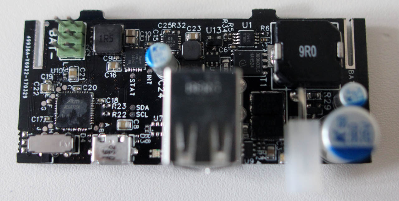
For those interested in using the programming and GPIO functionality, but don't want to use the PC interface, there is a TTL serial port onboard on the 6-pin PDI header (top-left of the board photo). This UART mirrors exactly the virtual serial port over USB, with the only exception that virtual ports do not have a defined baud rate. The default baud rate on this port is 9600 with 8-bit data, no parity, 1 stop bit (9600/8N1). This can be changed through either USB or the serial port itself. Note that the pinout is exactly the same as an AVR PDI programming port, but with the unused middle pins assigned TX and RX. The designations TX and RX are from the MCU's perspective.

Also present on the board are 9 GPIOs. These can be programmed using the bytecode programming language documented below. The GPIOs are labeled on board A-J, and can perform the following functionality:
- GPIO A: Digital input/output
- GPIO B: Digital input/output
- GPIO C: Digital input/output, ADC with 0-1V input range, Analog Comparator positive or negative input.
- GPIO D: Digital input/output, ADC with 0-1V input range, Analog Comparator positive input.
- GPIO E: Digital input/output, ADC with 0-1V input range, Analog Comparator positive or negative input
- GPIO F: Digital input/output, ADC with 0-1V input range, Analog Comparator positive input.
- GPIO G: Digital input/output, ADC with 0-1V input range, Analog Comparator negative input.
- GPIO H: Digital input/output, PWM output (3.3V, 0Hz-8MHz, any duty, timer shared with GPIO J), UART RX.
- GPIO J: Digital input/output, PWM output (3.3V, 0Hz-8MHz, any duty, timer shared with GPIO H), UART TX.
This functionality can be changed in runtime.
Programming the powerbank
State machine
The powerbank continuously updates an internal state machine which governs most of its behaviour. Most commands and responses of the powerbank pertain to this state machine. It contains the following information:
| Bit | 7 | 6 | 5 | 4 | 3 | 2 | 1 | 0 |
| +0x00 | TEMP[7:0] |
| +0x01 | TEMP[15:8] |
| Reset value | 0 | 0 | 0 | 0 | 0 | 0 | 0 | 0 |
- +0x00 and +0x01 TEMP: Temperature
This 16-bit signed integer (2's complement) contains the temperature at the location of the microcontroller in Celcius, in 0.1°C increments.
| Bit | 7 | 6 | 5 | 4 | 3 | 2 | 1 | 0 |
| +0x02 | VBAT[7:0] |
| +0x03 | VBAT[15:8] |
| Reset value | 0 | 0 | 0 | 0 | 0 | 0 | 0 | 0 |
- +0x02 and +0x03 VBAT: Battery voltage
This 16-bit signed integer (2's complement) contains the battery voltage as measured near the charger chip in mV.
| Bit | 7 | 6 | 5 | 4 | 3 | 2 | 1 | 0 |
| +0x04 | ILIM[7:0] |
| +0x05 | ILIM[15:8] |
| Reset value | 0 | 0 | 0 | 0 | 0 | 0 | 0 | 0 |
- +0x04 and +0x05 ILIM: Charging current
This 16-bit signed integer (2's complement) contains the charging current going into the battery in mA. This information can be used together with VBAT to calculate the battery capacity (Wh or Ah) as the battery charges.
| Bit | 7 | 6 | 5 | 4 | 3 | 2 | 1 | 0 |
| +0x06 | IOUT[7:0] |
| +0x07 | IOUT[15:8] |
| Reset value | 0 | 0 | 0 | 0 | 0 | 0 | 0 | 0 |
- +0x06 and +0x07 IOUT: HV output current
This 16-bit signed integer (2's complement) contains the output current on the HV output in mA. This can be used in combination with the output voltage VSET and typical converter efficiency of 80-90% (higher at higher output voltage) to estimate the power consumption from the powerbank. Note that the absolute accuracy of this measurement can be very poor in certain circumstances. In order to get accurate measurements, make sure the powerbank is not currently charging and turn off the USB output.
| Bit | 7 | 6 | 5 | 4 | 3 | 2 | 1 | 0 |
| +0x08 | I5V[7:0] |
| +0x09 | I5V[15:8] |
| Reset value | 0 | 0 | 0 | 0 | 0 | 0 | 0 | 0 |
- +0x08 and +0x09 I5V: USB output current
This 16-bit signed integer (2's complement) contains the combined output current on the USB type-A ports in mA. This can be used in combination with the output voltage of 5.25V and typical converter efficiency of 85% to estimate the power consumption from the powerbank. Note that the absolute accuracy of this measurement can be very poor in certain circumstances. In order to get accurate measurements, make sure the powerbank is not currently charging and turn off the HV output.
| Bit | 7 | 6 | 5 | 4 | 3 | 2 | 1 | 0 |
| +0x0A | VSET[7:0] |
| +0x0B | VSET[15:8] |
| Reset value | 0 | 0 | 0 | 0 | 0 | 0 | 0 | 0 |
- +0x0A and +0x0B VSET: HV output voltage
This 16-bit signed integer (2's complement) contains the output voltage on the HV port in mV. Note that this value is not valid when the output is disabled (it will read a very high voltage, even though the real voltage on the port is much less than the nominal voltage).
- +0x0C and +0x0D: Reserved
| Bit | 7 | 6 | 5 | 4 | 3 | 2 | 1 | 0 |
| +0x0E | GPC[7:0] |
| +0x0F | GPC[15:8] |
| Reset value | 0 | 0 | 0 | 0 | 0 | 0 | 0 | 0 |
- +0x0E and +0x0F GPC: Voltage on GPIO C
This 16-bit signed integer (2's complement) contains the voltage present on GPIO C in mV, with a maximum input range of 0-1.000V. Any higher voltage value will be clipped. If this output is configured as a digital I/O or analog comparator, this value will be invalid.
| Bit | 7 | 6 | 5 | 4 | 3 | 2 | 1 | 0 |
| +0x10 | GPD[7:0] |
| +0x11 | GPD[15:8] |
| Reset value | 0 | 0 | 0 | 0 | 0 | 0 | 0 | 0 |
- +0x10 and +0x11 GPD: Voltage on GPIO D
This 16-bit signed integer (2's complement) contains the voltage present on GPIO D in mV, with a maximum input range of 0-1.000V. Any higher voltage value will be clipped. If this output is configured as a digital I/O or analog comparator, this value will be invalid.
| Bit | 7 | 6 | 5 | 4 | 3 | 2 | 1 | 0 |
| +0x12 | GPE[7:0] |
| +0x13 | GPE[15:8] |
| Reset value | 0 | 0 | 0 | 0 | 0 | 0 | 0 | 0 |
- +0x12 and +0x13 GPE: Voltage on GPIO E
This 16-bit signed integer (2's complement) contains the voltage present on GPIO E in mV, with a maximum input range of 0-1.000V. Any higher voltage value will be clipped. If this output is configured as a digital I/O or analog comparator, this value will be invalid.
| Bit | 7 | 6 | 5 | 4 | 3 | 2 | 1 | 0 |
| +0x14 | GPF[7:0] |
| +0x15 | GPF[15:8] |
| Reset value | 0 | 0 | 0 | 0 | 0 | 0 | 0 | 0 |
- +0x14 and +0x15 GPC: Voltage on GPIO F
This 16-bit signed integer (2's complement) contains the voltage present on GPIO F in mV, with a maximum input range of 0-1.000V. Any higher voltage value will be clipped. If this output is configured as a digital I/O or analog comparator, this value will be invalid.
| Bit | 7 | 6 | 5 | 4 | 3 | 2 | 1 | 0 |
| +0x16 | GPG[7:0] |
| +0x17 | GPG[15:8] |
| Reset value | 0 | 0 | 0 | 0 | 0 | 0 | 0 | 0 |
- +0x16 and +0x17 GPG: Voltage on GPIO G
This 16-bit signed integer (2's complement) contains the voltage present on GPIO G in mV, with a maximum input range of 0-1.000V. Any higher voltage value will be clipped. If this output is configured as a digital I/O or analog comparator, this value will be invalid.
| Bit | 7 | 6 | 5 | 4 | 3 | 2 | 1 | 0 |
| +0x18 | BQ24295_REG00 |
| +0x19 | BQ24295_REG01 |
| +0x1A | BQ24295_REG02 |
| +0x1B | BQ24295_REG03 |
| +0x1C | BQ24295_REG04 |
| +0x1D | BQ24295_REG05 |
| +0x1E | BQ24295_REG06 |
| +0x1F | BQ24295_REG07 |
| +0x20 | BQ24295_REG08 |
| +0x21 | BQ24295_REG09 |
| Reset value | 0 | 0 | 0 | 0 | 0 | 0 | 0 | 0 |
- +0x18-0x21: BQ24295 REG00-REG09
These are the i2c-accessible registers from the BQ24295 charger chip. Please refer to the BQ24295 datasheet for a detailed description of these registers.
| Bit | 7 | 6 | 5 | 4 | 3 | 2 | 1 | 0 |
| +0x22 | AUTOSEND | CDC | PLUGGED_IN | WARN_EN | CHRG_FAULT | BAT_FAULT | NTC_COLD | NTC_HOT |
| Reset value | 0 | 0 | 0 | 0 | 0 | 0 | 0 | 0 |
- +0x22 bit 7 AUTOSEND: automatically send statemachine
This bit, if set (using command 0x47) or toggled on (using command 0x46), will cause the powerbank to periodically send the entire state machine over the (virtual) serial port. For revision 3, this period is approx. 400ms. This bit does not affect other messages sent by the powerbank (e.g. warnings or command responses)
- +0x22 bit 6 CDC: Virtual serial port connected
This bit tracks whether the powerbank currently has a virtual serial port set up over USB to a host computer. This bit does not indicate active communications, only successful USB enumeration.
- +0x22 bit 5 PLUGGED_IN: Charging port plugged in
This bit tracks whether the powerbank currently is receiving power via the charging port. If bit 4 (WARN_EN) is enabled, a warning will be sent when the powerbank is unplugged.
- +0x22 bit 4 WARN_EN: Enable warnings
If this bit is set (using command 0x79 - disable this bit with 0x7A), warnings will be sent over USB when:
- The powerbank is plugged in
- The powerbank is unplugged
- A charger fault is detected (bit CHRG_FAULT turns on)
- Battery overvoltage is detected (bit BAT_FAULT turns on)
- The battery is too cold to charge (bit NTC_COLD turns on)
- The battery is too hot (bit NTC_HOT turns on)
- +0x22 bit 3 CHRG_FAULT: Charger fault
This bit is set when the charger encounters a fault; either because the charger IC overheats, the input power source voltage is too high or the charge timer has expired (by default the charge timer is off, see bq24295 datasheet)
- +0x22 bit 2 BAT_FAULT: Battery overvoltage
This bit is set when the charger chip measures an overvoltage on the battery.
- +0x22 bit 1 NTC_COLD: Battery too cold
This bit is set when the battery is too cold to charge (typically -10°C or lower)
- +0x22 bit 0 NTC_HOT: Battery too hot
This bit is set when the battery is too hot to charge (typically 55°C or higher)
| Bit | 7 | 6 | 5 | 4 | 3 | 2 | 1 | 0 |
| +0x23 | HV_ON | USB_ON | Reserved |
| Reset value | 0 | 0 | 0 | 0 | 0 | 0 | 0 | 0 |
- +0x23 bit 7 HV_ON: HV output on
This bit is on when the HV output is on
- +0x23 bit 6 USB_ON: USB output on
This bit is on when the USB output is on
| Bit | 7 | 6 | 5 | 4 | 3 | 2 | 1 | 0 |
| +0x24 | ON_TIME[7:0] |
| +0x25 | ON_TIME[15:8] |
| +0x26 | ON_TIME[23:16] |
| +0x27 | ON_TIME[31:24] |
| Reset value | 0 | 0 | 0 | 0 | 0 | 0 | 0 | 0 |
- +0x24-0x27 ON_TIME: Time since last reset
This 32-bit value tracks the number of seconds since the last reset (the uptime of the battery pack)
| Bit | 7 | 6 | 5 | 4 | 3 | 2 | 1 | 0 |
| +0x28 | SIGNATURE[0] |
| +0x29 | SIGNATURE[1] |
| +0x2A | SIGNATURE[2] |
| +0x2B | SIGNATURE[3] |
| +0x2C | SIGNATURE[4] |
| +0x2D | SIGNATURE[5] |
| +0x2E | SIGNATURE[6] |
| +0x2F | SIGNATURE[7] |
| +0x30 | SIGNATURE[8] |
| +0x31 | SIGNATURE[9] |
| +0x32 | SIGNATURE[10] |
| Reset value | 0 | 0 | 0 | 0 | 0 | 0 | 0 | 0 |
- +0x28-0x32 SIGNATURE: MCU production signature
This array contains the full production signature of the Microchip ATXMega32C4 in the powerbank, which consists of:
- 6 lot number bytes
- 1 wafer number byte
- 2 wafer coordinate X bytes
- 2 wafer coordinate Y bytes
Serial commands and responses
The Muxtronics programmable powerbank can be instructed to perform certain actions and report certain variables using commands over the (virtual) serial port. Some commands will return responses, others only perform an action.
| Command | ASCII | Action | Response |
| 0x41 | A | Send signature bytes | A 13-byte long response containing the 11-byte signature + 'S\n' |
| 0x42 | B | Request user-defined name | An 18-byte long response containing the 16-byte user-defined powerbank name + 'N\n' |
| 0x43 + 16 bytes | C + 16 bytes | Program user-defined name. The powerbank expects the 16 bytes after 0x43 to be the name. If no bytes are provided, this can lock up the microcontroller | Same as 0x42 |
| 0x46 | F | Toggles the state of AUTOSEND (statemachine +0x20 bit 7) and causes the powerbank to periodically send the state machine if toggled on. | 'autosend raw data ON \n' (length 24)
'autosend raw data OFF \n' (length 24) |
| 0x47 | G | Turns the state of AUTOSEND on. See 0x46. | 'autosend raw data ON \n' (length 24) |
| 0x48 | H | Turns the state of AUTOSEND off. See 0x46 | 'autosend raw data OFF \n' (length 24) |
| 0x70 | p | Sends the state machine. Refer to 0x46 for more information | (nothing) |
| 0x71 + 0-9 + 00-FF | q + 0-9 + 00-FF | Set the value of a bq24295 register. This command expects the register number in ascii (i.e. a number between 0-9 inclusive), 1 byte, and then the hexadecimal representation of the register value (ASCII, capital letters, 2 bytes) to be programmed to follow the command. Failing to send these bytes may lock up the microcontroller. | (nothing) |
| 0x72 | r | Request uptime | '00000000000U\n' with 0's replaced by uptime in seconds (length 13) |
| 0x73 | s | Increase output voltage by 1 step (total: 64 steps) | (nothing) |
| 0x74 | t | Decrease output voltage by 1 step (total: 64 steps) | (nothing) |
| 0x75 | u | Enable USB output | (nothing) |
| 0x76 | v | Disable USB output | (nothing) |
| 0x77 | w | Enable HV output | (nothing) |
| 0x78 | x | Disable HV output | (nothing) |
| 0x79 | y | Enable warnings (see statemachine +0x20 bit 4 WARN_EN) | (nothing) |
| 0x7A | z | Disable warnings (see statemachine +0x20 bit 4 WARN_EN) | (nothing) |
| 0xFF | N/A | Request descriptive identifier string | 'Muxtronics Powerbank rev3\n' (length 24) |